5.10 Accessory Uses, Buildings and Structures
| 1. | Any Use may be Accessory to a listed Use in the Zone, if the Use complies with the definition of Accessory in the Bylaw. | |||||||
| 2. | Despite Subsection 1, Signs must not be approved as an Accessory Use. | |||||||
| 3. | An Accessory building or structure must not be used for residential living purposes. | |||||||
| 4. | Where a building or structure on a Site is attached to a principal building: | |||||||
|
||||||||
| 5. | Unless otherwise provided in this Bylaw, an Accessory building or structure on a Corner Site or a Double Fronting Site is subject to the Front Setback requirements, where Front Lot Lines are determined through Section 5.130. | a | ||||||
| 6. | An Accessory building or structure in a non-residential Zone must comply with the development regulations of the underlying Zone. | |||||||
| 7. | Unless otherwise stated in this Bylaw, Accessory buildings in the RS and RSF Zones, or a residential Zone with a maximum Height of 12.0 m or less, are exempt from building facade design requirements. | a | ||||||
| 8. | For Zero Lot Line Development, an Accessory building or structure must not encroach on the easement area, except for eaves and footings as permitted by a private easement. | |||||||
| 9. | Unless otherwise specified in this Bylaw, Accessory buildings or structures located in residential Zones must comply with Table 9: | |||||||
| Table 9. Accessory Building or Structures Regulations | ||||
|---|---|---|---|---|
| Subsection | Regulation | Value | Symbol | |
| 9.1. | Maximum Height | 4.3 m | - | |
| 9.2. | Maximum Site Coverage | 20% | - | |
| Setbacks | ||||
| 9.3. | Minimum Setback | 0.6 m | A | |
| Unless 1 or more of the following applies: | ||||
| 9.4. | Minimum Setback from the Garage door of a detached Garage where the door faces an Alley | 1.2 m | B | |
| 9.5. | Minimum Rear or Interior Side Setback for an Accessory building that has a maximum Height less than or equal to 2.4 m measured to the peak of the roof | 0 m | - | |
| 9.6. | Minimum Setback between an Accessory building and at least 1 Interior Side Lot Line where a Site is developed as Reverse Housing | 1.2 m | C | |
|
Diagram for Section 8.3, 8.4, and 8.6 a 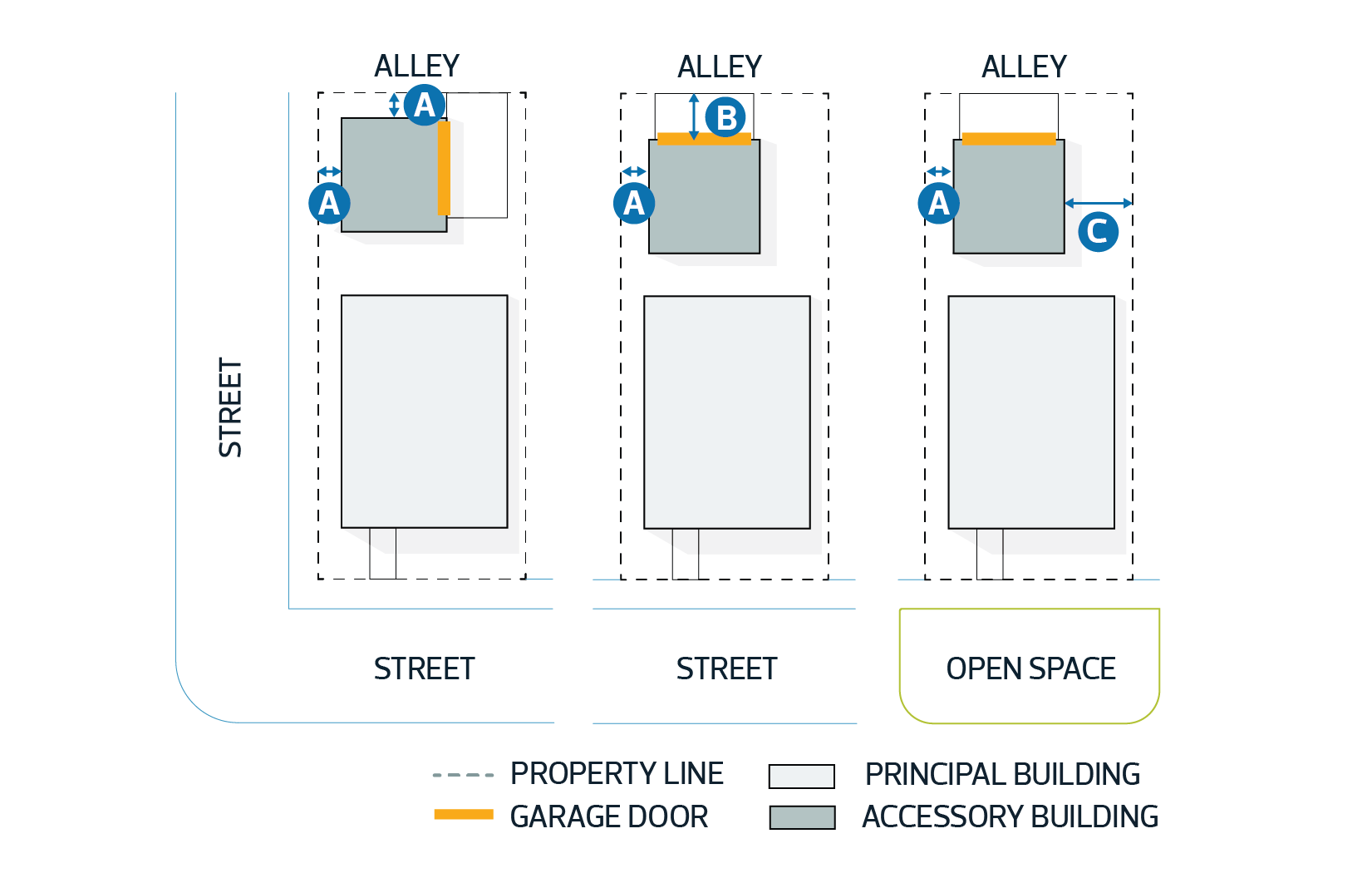
|
||||
| 9.7. | Minimum Interior Side Setback where a mutual Garage is built on a common Lot line | 0 m | - | |
| 9.8. | Minimum Interior Side Setback where the building is Accessory to a Zero Lot Line Development and meets the requirements of Subsection 6.4 of the RSF Zone | 0 m | - | |
| Accessory Building Location | ||||
| 9.9. | Accessory buildings are not permitted in a Front Yard | - | - | |
| 9.10. | Minimum distance between an Accessory building and any other building on the same Site | 0.9 m | - | |
| 9.11. | Where an Interior Side Setback of an Accessory building is less than 0.3 m, the building must not obstruct a required drainage swale | - | - | |
| 10. | There is no minimum distance between swimming pools, hot tubs, rinks, ornamental ponds, and similar features and a principal building or Accessory building or structure. | ||
| 11. | Swimming pools, ornamental ponds, flagpoles, ornaments, or similar features may be located in a Setback, except that: | ||
|
Solar Collectors
| 12. | Solar Collectors must comply with the following: | ||||||
|
5.20 Amenity Areas
| 1. | Developments with more than 8 Dwellings must provide a minimum Amenity Area of 7.5 m2 per Dwelling, except that: | ||||||||||
|
|||||||||||
| 2. | Each Dwelling or Sleeping Unit must have access to required Amenity Areas, provided as a Private Outdoor Amenity Area or Common Amenity Area. | ||||||||||
| 3. | The minimum length and width of a required Amenity Area is 1.5 m. | ||||||||||
| 4. | Where a required Amenity Area Abuts an Arterial Road, a minimum Setback of 1.0 m must be provided. | ||||||||||
| 5. | The boundary of required Amenity Areas at ground level must be defined by incorporating Fencing or Landscaping elements such as planters, hedges, hard or soft surface treatments such as Pathways, or raised structures. | ||||||||||
Outdoor Common Amenity Area Regulations |
|||||||||||
| 6. | Where required Amenity Area is provided as outdoor Common Amenity Area, it must: | ||||||||||
|
|||||||||||
Indoor Common Amenity Area Regulations |
|||||||||||
| 7. | Where required Amenity Area is provided as indoor Common Amenity Area, it must: | ||||||||||
|
|||||||||||
| 8. | Where provided, indoor Common Amenity Areas are not included in the calculation of Floor Area Ratio. | ||||||||||
5.30 Bare Land Condominium
| 1. | For the purpose of issuing a Development Permit, each Bare Land Condominium Unit must be considered an independent Site. | ||||||||||||||||||||
| 2. | Where a Bare Land Condominium is served by a private roadway, the following applies: | ||||||||||||||||||||
|
|||||||||||||||||||||
5.40 Excavation, Stripping and Grading
| 1. | For the purpose of this Section, excavation means excavation other than for construction or building purposes, including but not limited to: | ||||||||||||||||
|
|||||||||||||||||
| 2. | To undertake Site excavation, stripping, or grading of land, an application for a Development Permit must provide: | ||||||||||||||||
|
|||||||||||||||||
| 3. | For every Development Permit application to undertake Site excavation, stripping or grading of land, the Development Planner must be satisfied that the operation will: | ||||||||||||||||
|
|||||||||||||||||
| 4. | The Development Planner must apply conditions to ensure that: | ||||||||||||||||
|
5.50 Inclusive Design
Applicability
| 1. | Where this Section is referenced in a Zone, development must achieve the minimum requirements for inclusive design for: | |||||||||||||||||||||
|
||||||||||||||||||||||
Minimum Criteria for Shared Areas of a Building |
||||||||||||||||||||||
| 2. | The main entrance to a building in which the Dwelling or Sleeping Unit is located must: | |||||||||||||||||||||
|
||||||||||||||||||||||
| 3. | If there is no direct exterior access at ground level to the Dwelling or Sleeping Unit, an internal Barrier-free path of travel with a minimum width of 1.8 m must be provided from the main entrance of the building to the Dwelling or Sleeping Unit. | |||||||||||||||||||||
| 4. | If the entrance to the Dwelling or Sleeping Unit is not on the Ground Floor, that Dwelling or Sleeping Unit must be accessible by an elevator. | |||||||||||||||||||||
| 5. | Indoor Common Amenity Areas and other shared facilities must be accessible from the Dwelling or Sleeping Unit by a Barrier-free path of travel with a minimum width of 1.8 m. | |||||||||||||||||||||
| 6. | The impact of a long Barrier-free path of travel must be minimized by including areas for seating at regular intervals, which must not obstruct the Barrier-free path of travel. | |||||||||||||||||||||
| 7. | All doorways along a Barrier-free path of travel must provide a minimum unobstructed width of 0.9 m. | |||||||||||||||||||||
| 8. | A minimum 1.8 m unobstructed turning diameter must be provided along all areas of a Barrier-free path of travel. | |||||||||||||||||||||
Minimum Criteria for Dwellings |
||||||||||||||||||||||
| 9. | All entrances to the Dwelling must: | |||||||||||||||||||||
|
||||||||||||||||||||||
| 10. | All areas within the Dwelling must provide a Barrier-free path of travel with a minimum width of 1.2 m. | |||||||||||||||||||||
| 11. | A minimum 1.5 m unobstructed turning diameter must be provided in all areas of the Dwelling, including but not limited to: | |||||||||||||||||||||
|
||||||||||||||||||||||
| 12. | Despite Subsection 11, where provided, balconies and patios must provide a minimum 1.8 m unobstructed turning diameter and Barrier-free access. | |||||||||||||||||||||
| 13. | All doorways within the Dwelling must have a minimum unobstructed width of 0.9 m. | |||||||||||||||||||||
| 14. | The following must be included on the same floor as the Barrier-free entrance to the Dwelling: | |||||||||||||||||||||
|
||||||||||||||||||||||
| 15. | Despite Subsection 14, a bathroom, kitchen, laundry facility, and bedroom are not required to be on the same floor as a Barrier-free entrance to the Dwelling where a stair lift or elevator provides Barrier-free access to these facilities. | a | ||||||||||||||||||||
| 16. | If the Dwelling contains more than 1 Storey, and an elevator or stair lift is not provided at the time of construction, the Dwelling must be designed to accommodate the installation of a stair lift or elevator. | a | ||||||||||||||||||||
|
||||||||||||||||||||||
Minimum Criteria for Sleeping Units |
||||||||||||||||||||||
| 17. | At least 1 entrance to the Sleeping Unit must: | |||||||||||||||||||||
|
||||||||||||||||||||||
| 18. | All areas within the Sleeping Unit must provide a Barrier-free path of travel with a minimum width of 1.2 m. | |||||||||||||||||||||
| 19. | A minimum 1.5 m unobstructed turning diameter must be provided in all areas of the Sleeping Unit. | |||||||||||||||||||||
| 20. | All doorways within the Sleeping Unit must have a minimum unobstructed width of 0.9 m. | |||||||||||||||||||||
| 21. | At least 1 bathroom must be included on the same floor as, or within, the Sleeping Unit that includes: | |||||||||||||||||||||
|
a | |||||||||||||||||||||
5.60 Landscaping
To ensure a baseline standard of Landscaping for development, from the initial placement of the Landscaping through to its maturity, and to help support more livable and attractive development, encourage environmental stewardship, and to contribute to Edmonton’s urban forest, biodiversity, and The City Plan’s climate resiliency goals.
| 2.1. | The requirement for Landscaping must be a condition of a Development Permit, except where a proposed development: | |||||||||||
|
||||||||||||
| 2.2. | All open space, including Yards, Setback areas, and Common Amenity Areas must be Landscaped with trees, shrubs, flowers, grass, or other perennial ground cover, except where the open space is: | |||||||||||
|
||||||||||||
| 2.3. | Landscaping on City-owned land must comply with applicable Traffic Bylaw, Bylaw 5590 and the City Design and Construction Standards, to the satisfaction of the Development Planner in consultation with the appropriate City department. | a | ||||||||||
| 2.4. | Before granting a variance to a Landscaping requirement within this Bylaw, the Development Planner may require the applicant to submit a report justifying the variance from a qualified landscape professional, such as a horticulturist, arborist, landscape architect, or landscape architectural technologist. | |||||||||||
| 3.1 | Trees and shrubs for Single Detached Housing, Duplex Housing, Semi-detached Housing, and Row Housing, excluding Cluster Housing developments, must comply with Table 3.1: |
| Table 3.1. Minimum Trees and Shrubs | ||
|---|---|---|
| Subsection | Measure | Minimum Tree and Shrub Requirements |
| Single Detached Housing, Semi-detached Housing, and Duplex Housing | ||
| 3.1.1. | Where the Site Width is less than 8.0 m | 1 tree and 4 shrubs |
| 3.1.2. | Where the Site Width is 8.0 m - 15.0 m | 2 trees and 6 shrubs |
| 3.1.3. | Where the Site Width is greater than 15.0 m | 4 trees and 8 shrubs |
| Row Housing | ||
| 3.1.4. | Per principal Dwelling | 1 tree and 4 shrubs |
Minimum Soft Landscaping Area
| 3.2 | A minimum Soft Landscaped area equal to 30% of the total Lot area must be provided for: | ||||||
|
|||||||
| 3.3. | Despite Subsection 3.2, a minimum Soft Landscaped area equal to 25% of the total Lot area must be provided: | ||||||
|
|||||||
| 3.4. | Despite the definition of Soft Landscaping, the area of building coverage developed with a Green Roof is included in the calculation of Soft Landscaping on a Site. |
| 4.1. | Trees and shrubs for all development not regulated in Subsection 3.1 must comply with Table 4.1: |
| Table 4.1. Minimum Trees and Shrubs | ||
|---|---|---|
| Subsection | Measure | Minimum Tree and Shrub Requirements |
All development, excluding development: - regulated in Subsection 3.1 and Backyard Housing; | ||
| 4.1.1. | Total Setback area, calculated based on the Setbacks at ground level | 1 tree and 2 shrubs per 30.0 m2 |
| 4.1.2. | Length of Pathways along internal Streets and private roads, for Sites greater than or equal to 2 ha that are in a commercial or mixed use Zone | 1 deciduous tree per 10.0 m |
| 4.1.3. | The total Public Amenity Area or Park area with a depth greater than 3.0 m between a Lot line Abutting a Street and a building, for Sites in the MU Zone | 1 tree and 2 shrubs per 30 m2 |
| Development on Sites in the PS or PSN Zone | ||
| 4.1.4. | For non-City owned Sites, total area, excluding building footprints and sports field playable areas | 55 trees per ha |
| 4.2. | For the purposes of calculating Subsection 4.1.1, the portion of the Setback area that Abuts a Street and is directly in front of a Ground Floor non-Residential Use in a mixed use Zone is excluded from the calculation of the total Setback area. | ||||||||||||||||||||
| 4.3. | For Sites in an industrial Zone, a Landscape Buffer must be provided to screen outdoor storage and outdoor activities associated with an Industrial Use on Sites Abutting the following Streets or corridors: | ||||||||||||||||||||
| |||||||||||||||||||||
Parking, Waste Collection, Storage and Service Areas | |||||||||||||||||||||
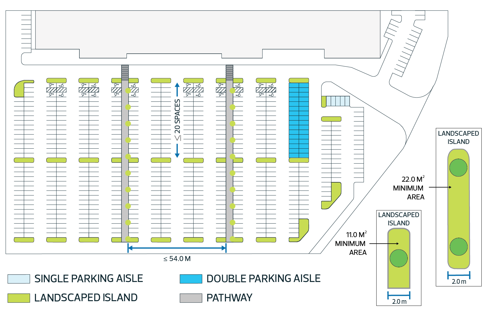
| 4.4. | Landscaping must be provided to shade and enhance the appearance of Surface Parking Lots, Landscaped islands, and along Pathways within Surface Parking Lots, to the satisfaction of the Development Planner. | ||||||||||||||||||||
| 4.5. | Trees and shrubs within Landscaped islands and along Pathways within Surface Parking Lots as specified in Section 5.80 must be well suited to survive in high-traffic areas and comply with Table 4.5: | ||||||||||||||||||||
| Table 4.5. Minimum Trees and Shrubs | ||
|---|---|---|
| Subsection | Measure | Minimum Tree and Shrub Requirements |
| Per Landscaped Island | ||
| 4.5.1. | Landscaped islands up to 11.0 m2 | 1 tree and 2 shrubs |
| 4.5.2. | Landscaped islands greater than 11.0 m2 and up to 22.0 m2 | 2 trees and 4 shrubs |
| 4.5.3. | Landscaped islands greater than 22.0 m2 | 2 trees and 4 shrubs up to 22.0 m2; and 1 tree and 2 shrubs for each additional 22.0 m2 |
| Along Pathways within Surface Parking Lots | ||
| 4.5.4. | Length of Pathways | 1 deciduous tree per 10.0 m |
| 4.6. | To enhance the view and soften the edge along Surface Parking Lots, trees and shrubs must be provided along the perimeter of Surface Parking Lots Abutting Streets or other Sites, except that: | ||
| |||
| 4.7. | Waste collection areas, open storage areas, and outdoor service areas, including loading, unloading, or vehicle service areas, must be screened from view from Abutting non-industrial Zones, Streets, and light rail transit lines with a Landscape Buffer that has a minimum Height of 1.8 m. |
| 5.1. | The Development Planner may require additional Landscaping above the minimum trees and shrubs required in this Bylaw: | ||||||
|
|||||||
| 5.2. | Landscape Buffers provided to meet a requirement in this Bylaw must comply with the following, to the satisfaction of the Development Planner: | ||||||
|
|||||||
| 5.3. | Where the Development Planner requires additional Landscaping, they may consult with a qualified landscape professional, such as a horticulturist, arborist, landscape architect, or landscape architectural technologist to determine the amount and type of additional Landscaping required. | ||||||
| 5.4. | Where, in the opinion of the Development Planner, a required Landscape Buffer for the purpose of screening is not reasonably expected to survive, berms, masonry walls, Fences or other similar features may be required. |
| 6.1. | New trees and shrubs must comply with the following: | ||||||||||
|
| 7.1. | Existing plant material should be preserved and protected unless removal is demonstrated to be necessary or desirable to accommodate a proposed development. |
| 7.2. | Tree and shrub requirements may be satisfied by preserving existing trees and shrubs at the rates specified in Table 7.2: |
| Table 7.2. Substituting Required Trees or Shrubs | ||
|---|---|---|
| Subsection | Requirement | Preserved Trees or Shrubs that can be Substituted |
| 7.2.1. | 2 trees | 1 existing deciduous tree with a minimum 100 mm Caliper; or 1 existing coniferous tree with a minimum Height of 4.0 m |
| 7.2.2. | 3 trees | 1 existing deciduous tree with a minimum 200 mm Caliper; or 1 existing coniferous tree with a minimum Height of 7.0 m |
| 7.2.3. | 1 shrub | 1 existing deciduous shrub with a minimum Height of 300 mm; or 1 existing coniferous shrub with a minimum spread of 450 mm |
| 7.3. | The Development Planner must, where applicable in consideration of Subsections 7.1 and 7.2, require mitigation measures in compliance with Subsections 8.7 and 8.8 to protect existing trees and shrubs intended to meet Landscaping requirements. |
| 8.1. | Trees and shrubs must be provided within a planting bed with proper mulch to support better growing conditions and plant survival. | ||||||
| 8.2. | Sufficient soil depths and volumes in planting areas, including in planters and above Parkades, must be provided to support suitable growing conditions, plant survival, and to accommodate the Landscaping intended for plant materials and ground cover. | ||||||
| 8.3. | Landscaping must integrate plant material that provides colour or interest throughout the year to enhance the appearance of the development during winter months. | ||||||
| 8.4. | Plant material must: | ||||||
|
|||||||
| 8.5. | Plant material must be installed at finished grade, except where this is not practical, planters may be used. | ||||||
| 8.6. | Landscaping located in planters or Green Roofs must have sufficient thermal insulation to support better growing conditions and plant survival. | ||||||
| 8.7. | The Development Planner may require that a Yard or Setback, or a portion of it, be unobstructed and undisturbed below or above ground level, or require mitigation measures specified in Subsection 8.8, to: | ||||||
|
|||||||
| 8.8. | Mitigation measures to protect existing Landscaping or provide an adequate growing environment for required Landscaping may include: | ||||||
|
| 9.1. | Required Landscaping for Single Detached Housing, Semi-detached Housing, Duplex Housing, and Row Housing where these developments are not part of a Cluster Housing development, or where Backyard Housing is the only principal building on the Site, must: | ||||
|
|||||
| 9.2. | Required Landscaping for Multi-unit Housing, Cluster Housing and all other development to which Subsection 4 applies, must: | ||||
|
Landscape Security Requirements
| 10.1. | As a condition of Development Permit approval, a landscape security in the form of an irrevocable letter of credit, cheque or landscape development bond must be provided prior to the release of the Development Permit for building permit review, for every application for Multi-unit Housing, Cluster Housing, and non-Residential development, excluding those listed in Subsection 2.1.
| a a | ||||||||||||
| 10.2. | The amount of the landscape security must be sufficient to cover the cost to install and maintain the required Landscaping, as determined by the Development Planner based on: | a | ||||||||||||
| a | |||||||||||||
| 10.3. | If at the time of the first landscape inspection the required Landscaping has been fully installed, the amount of the landscape security may be reduced to 20% of the Landscaping costs to ensure the required Landscaping is maintained in a healthy condition for a minimum of 24 months. | a | ||||||||||||
| 10.4. | Where a landscape security is submitted in the form of a cheque or other secure form of payment, the following applies: | |||||||||||||
| ||||||||||||||
| 10.5. | Where a landscape security is submitted in the form of a letter of credit, the following applies: | |||||||||||||
| ||||||||||||||
| 10.6. | Where a landscape security is submitted in the form of a landscape development bond, the following applies: | a | ||||||||||||
| ||||||||||||||
Inspections and Maintenance Period | ||||||||||||||
| 10.7. | To verify the installation of the required Landscaping and to initiate the maintenance period, the Development Planner: | |||||||||||||
| ||||||||||||||
| 10.8. | Landscape inspections must occur during the growing season between May 1 and September 30, unless otherwise permitted at the discretion of the Development Planner. | |||||||||||||
Enforcement and Use of the Landscape Security | ||||||||||||||
| 10.9. | The City may draw on the landscape security for the City’s use absolutely to install, maintain, or replace improperly maintained Landscaping required for the development if the Landscaping has not been: | |||||||||||||
| ||||||||||||||
| 10.10. | In the event the City uses funds from the landscape security to install, maintain, or replace improperly maintained Landscaping required for the development, the City must provide a report to the property owner or the owner's representative indicating how the funds from the landscape security were applied after installing, maintaining or replacing improperly maintained Landscaping required for the development. | |||||||||||||
| ||||||||||||||
| 11.1. | Single Detached Housing, Semi-detached Housing, Duplex Housing, and Row Housing, that is not part of a Cluster Housing development, must provide a Site plan with the following information: | ||||||||
|
|||||||||
| 11.2. | Every application for all other development not listed under Subsection 11.1 or Subsection 2.1, must include a landscape plan. | ||||||||
| 11.3. | Landscape plans must comply with: | ||||||||
|
|||||||||
| 11.4. | The Development Planner may consider an application for a Development Permit where the landscape plan does not provide all the information specified in the appropriate application form if, in the opinion of the Development Planner, the landscape plan is sufficient to show that the Landscaping requirements of the Bylaw will be met. | ||||||||
| 11.5. | The Development Planner may require the following information to ensure the Landscaping requirements of the Bylaw can be met: | ||||||||
|
|||||||||
| 11.6. | In addition to Subsection 11.5, a detailed landscape plan prepared by a landscape architect registered with the Alberta Association of Landscape Architects must be provided for development that include: | ||||||||
|
|||||||||
| 11.7. | The Development Planner must require Landscaping to be installed in accordance with an approved landscape plan as a condition of the Development Permit for applications of development specified in Subsection 11.2. Any changes to an approved landscape plan must be approved by the Development Planner before the Landscaping is installed. |
5.70 Measuring Height and Grade
Diagram for Subsections 1.1 to 1.3 
|

|
Hip and Gable Roofs
| 1.1. | The Height of a building with a hip or gable roof is measured from Grade to the midpoint of the highest roof. The midpoint of a roof is determined to be between the end of the eave (intersection of the fascia board and the top of the roof sheathing) and the top of the roof. | ||||||||||||||||||||
| 1.2. | Despite Subsection 1.1, where the side of a roof contains one or more Dormers and the combined width of the Dormers is wider than 1/3 of the width of the building wall underneath the Dormers, the maximum Height of the roof of the building must be measured to the midpoint of the roof of the Dormers. | ||||||||||||||||||||
| |||||||||||||||||||||
Mansard or Gambrel Roofs | |||||||||||||||||||||
| 1.3. | The Height of a building with a mansard or gambrel roof is measured from Grade to the midpoint of the highest roof. The midpoint of a roof is determined to be between the deck line and the top of the roof. | ||||||||||||||||||||
| |||||||||||||||||||||
Flat Roofs | |||||||||||||||||||||
| 1.4. | The Height of a building with a flat roof is measured from Grade to the midpoint of the highest parapet. The midpoint of a parapet is determined to be between the top of the roof deck and the top of the parapet. | ||||||||||||||||||||
| |||||||||||||||||||||
Other Roof Styles | |||||||||||||||||||||
| 1.5. | For all other roof styles, such as | ||||||||||||||||||||
| |||||||||||||||||||||
| the Development Planner must determine the Height of a building by applying 1 of the methods specified in Subsection 1.1 to 1.4. The chosen method must balance development rights with the land use impact on adjacent properties. | |||||||||||||||||||||
Other Structures | |||||||||||||||||||||
| 1.6. | For Platform Structures and unenclosed steps, including landings, Height is measured from the lowest point at ground level to the top of the structure, excluding rails and artificial embankments. | ||||||||||||||||||||
Height Exemptions | |||||||||||||||||||||
| 1.7. | The top of a roof is permitted to extend a maximum of 1.7 m above the maximum Height permitted in the applicable Zone. | ||||||||||||||||||||
| 1.8. | Despite Subsection 1.7, the top of the parapet for a flat roof is only permitted to be a maximum of 0.4 m above the maximum Height permitted in the applicable Zone. | ||||||||||||||||||||
| 1.9. | The following building structures or features have no Height limit in any Zone: | ||||||||||||||||||||
| |||||||||||||||||||||
| 1.10. | Despite Subsections 1.8 and 1.9, buildings in a residential Zone with a maximum Height of 12.0 m or less may have a rooftop enclosure provided for a stairway, elevator housing and associated landing area used only to access the Rooftop Terrace. The top of the enclosure must not be more than 3.0 m above the maximum Height of the Zone. | ||||||||||||||||||||
| |||||||||||||||||||||


| 2.1. | The Development Planner determines Grade by using 1 of the following methods that best ensures compatibility with surrounding development: | |||||||||||||||
|
||||||||||||||||
Alternative Methods for Determining Grade |
||||||||||||||||
| 2.2. | The Development Planner may use an alternative method other than those described in Subsection 2.1 to determine Grade. Any approved Development Permit using an alternative method under this Subsection must be a Discretionary Development. | |||||||||||||||
Submitting a Grading Plan |
||||||||||||||||
| 2.3. | Where a Development Permit application is submitted to construct, rebuild, or increase the Height of a building or structure, the applicant must submit a grading plan prior to construction to show the elevation at each corner of the Site and at each corner of the building. | |||||||||||||||
| 2.4. | The applicant must submit all information that the Development Planner requires to determine Grade by the method the Development Planner chooses. | |||||||||||||||


5.80 Parking, Access, Site Circulation, and Bike Parking
| 1.1. | All vehicle access locations and curb crossings require the approval of the Development Planner in consultation with the City department responsible for transportation planning. |
| 2.1. | Single Detached Housing, Duplex Housing, Semi-detached Housing, Backyard Housing, Row Housing, and Residential development in the form of Multi-unit Housing or Cluster Housing with 8 Dwellings or less, must comply with the following: | a | ||||||||||||||||||||||||||||||||||||||||||||||||||||||||
|
| |||||||||||||||||||||||||||||||||||||||||||||||||||||||||
| 3.1. | All non-Residential development and Residential development not listed in Subsection 2.1 must comply with the following: | ||||||||||||||||||||||||||||||||||||
|
General Design Regulations
| 4.1. | Surface Parking Lots and Parkades must be designed: | ||||||||||||||||||||||
|
|||||||||||||||||||||||
Parkade Design |
|||||||||||||||||||||||
| 4.2. | A Parkade must: | ||||||||||||||||||||||
|
|||||||||||||||||||||||
Surface Parking Lot Design |
|||||||||||||||||||||||
| 4.3. | Unless otherwise specified, a Surface Parking Lot must be located a minimum of 2.0 m from the Lot line of an Abutting Site, or the minimum required Setback in the underlying Zone, whichever is greater, except that: | ||||||||||||||||||||||
|
|||||||||||||||||||||||
| 4.4. | A Surface Parking Lot must be located a minimum of 3.0 m from a Lot line Abutting a Street, or the minimum required Setback Abutting a Street in the underlying Zone, whichever is greater. | ||||||||||||||||||||||
| 4.5. | Landscaping must be incorporated to shade and enhance the appearance of the Parking Area and Pathways, in compliance with Section 5.60. | ||||||||||||||||||||||
| 4.6. | Pathways within Surface Parking Lots must be provided so that there is no more than 54.0 m between Pathways. | ||||||||||||||||||||||
| 4.7. | Where a Surface Parking Lot has 30 or more parking spaces, it must contain Landscaped islands that comply with the following: | ||||||||||||||||||||||
|
|||||||||||||||||||||||
| a | |||||||||||||||||||||||
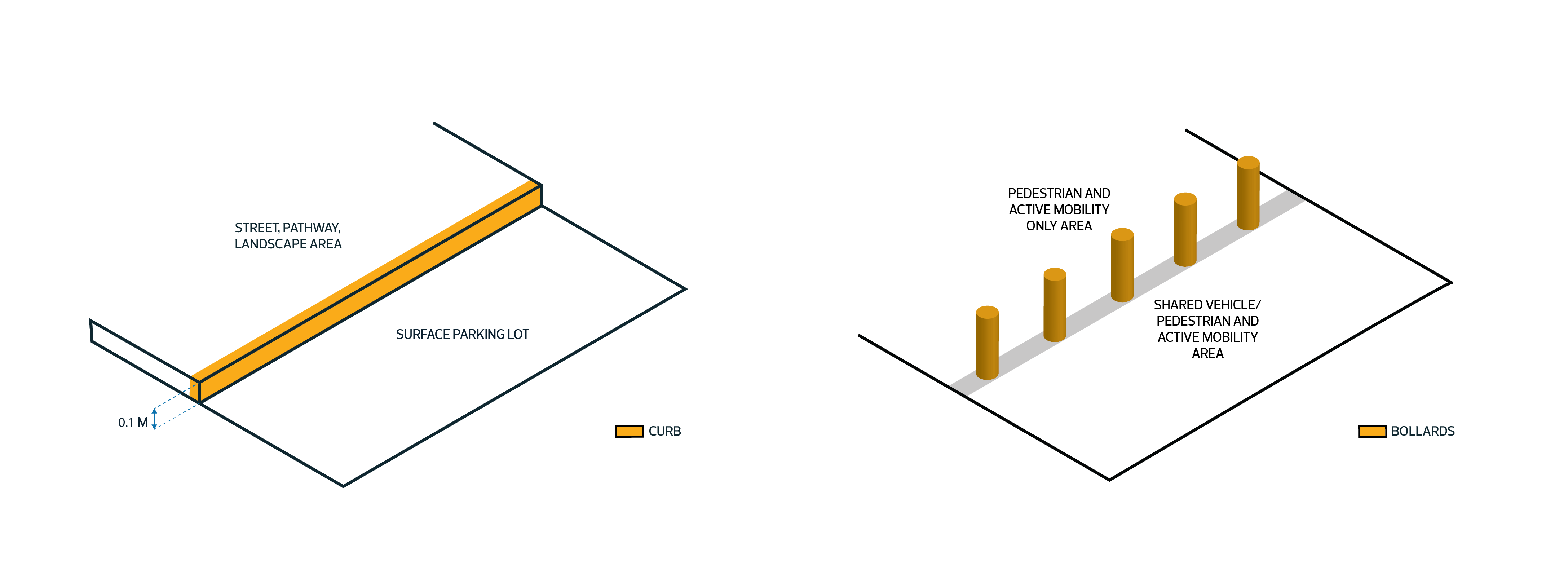
| 4.8. | Continuous raised or precast curbing a minimum of 0.1 m in Height must be provided within Surface Parking Lots adjacent to Streets, Pathways, sidewalks, and Landscaped areas, except that: | ||||||||||||||||||||||
|
|||||||||||||||||||||||
|
|||||||||||||||||||||||
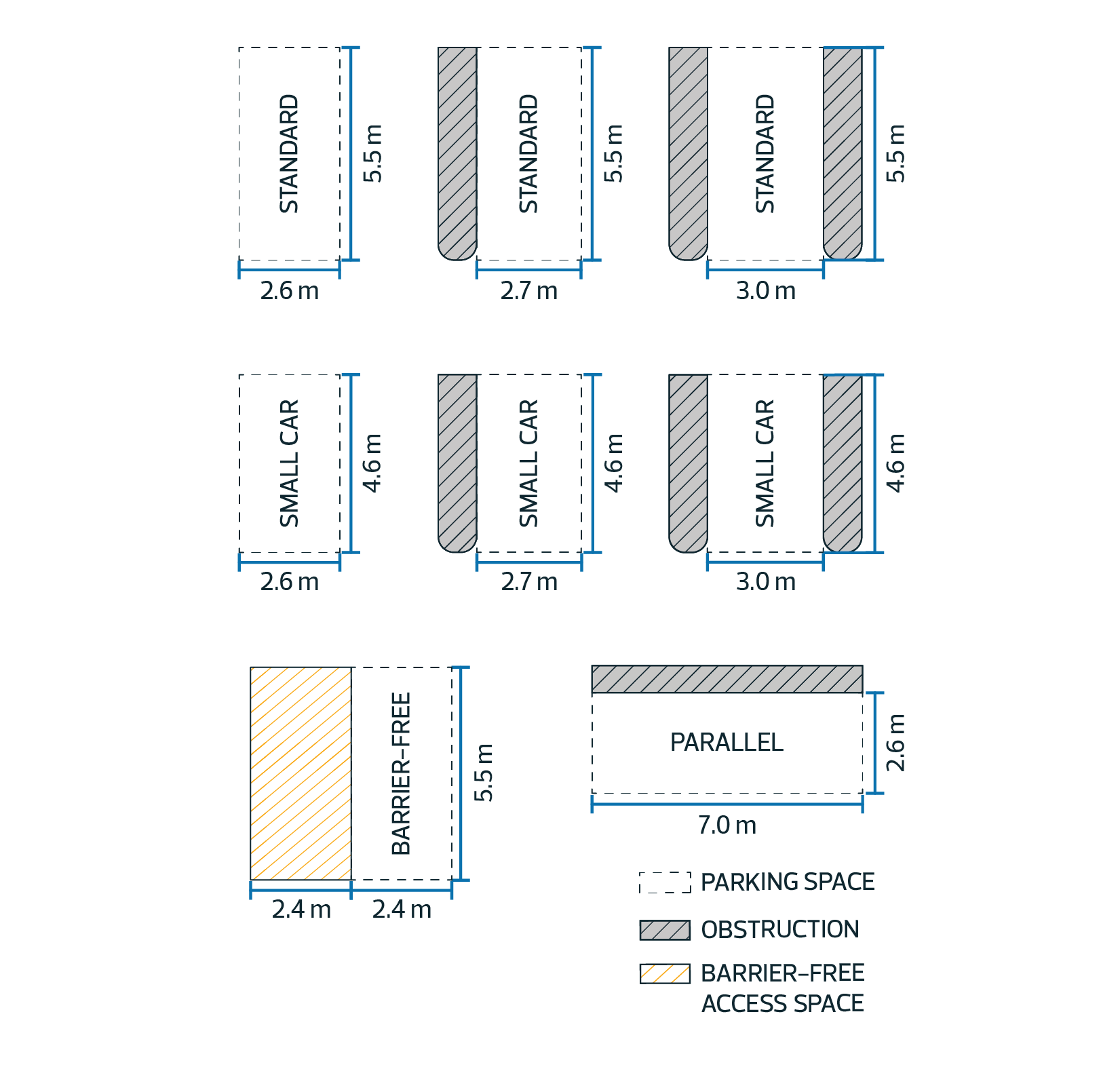
Parking Space Regulations
| 5.1. | Provided parking spaces must: | |||||||||||||||
|

| Table 5.1.3. Minimum Parking Space Design Requirements | ||||||
|---|---|---|---|---|---|---|
| Subsection | Parking Space Type | Length | Width | Vertical Clearance | Width with Obstruction on 1 Side | Width with Obstruction on Each Side |
| 5.1.3.1. | Standard | 5.5 m | 2.6 m | 2.1 m | 2.7 m | 3.0 m |
| 5.1.3.2. | Small car | 4.6 m | 2.6 m | 1.9 m | 2.7 m | 3.0 m |
| 5.1.3.3. | Barrier-free | 5.5 m | 2.4 m in compliance with Subsection 5.3 | 2.4 m | - | - |
| 5.1.3.4. | Parallel | 7.0 m | 2.6 m | 2.1 m | - | - |
|
|||||
| 5.2. | Small car parking spaces provided in compliance with Subsection 5.1.3.2 must: | ||||
|
|||||
| 5.3. | Barrier-free parking spaces provided in compliance with Subsections 5.1.3.3 and 6.6 must: | ||||
|
|||||
| 5.4. | Parking spaces provided as visitor parking for Residential developments must: | ||||
|
|||||
Drive Aisle Regulations |
|||||
| 5.5. | Drive Aisles must comply with Table 5.5: | ||||
| Table 5.5. Minimum Drive Aisle Widths | |||
|---|---|---|---|
| Subsection | Regulation | Width | Symbol |
| 5.5.1. | 90° parking spaces | 7.0 m | A |
| 5.5.2. | 60° parking spaces | 5.5 m | B |
| 5.5.3. | 45° parking and parallel parking spaces | 3.6 m | C |
Diagram for Subsection 5.5
|
|||
| 5.6. | Where access to a parking space is provided directly from an Alley, an on-Site Drive Aisle is not required, but the entire parking space must be provided on the Site. | |||||
Hard Surfacing Regulations |
||||||
| 5.7. | Unless otherwise specified, vehicle access, Parking Areas, Surface Parking Lots, and loading spaces must be Hard Surfaced where vehicle access is provided from a Street or an Alley. | a | ||||
| 5.8. | Despite Subsection 5.7, Hard Surfacing is not required: | |||||
|
||||||
| 5.9. | Despite Subsection 5.7, Driveways and Parking Areas for Residential developments specified in Subsection 2.1 may be provided as Hard Surfaced tire tracks. | a | ||||
Parking Maximums
| 6.1. | The maximum number of vehicle parking spaces permitted on a Site located within the boundaries of the Capital City Downtown Plan must comply with Tables 6.1.1 and 6.1.2: |
| Table 6.1.1. Maximum Number of Parking Spaces for Residential Uses Per Zone | |||||||||
|---|---|---|---|---|---|---|---|---|---|
| Subsection | Regulation | Zone | |||||||
| AED | CCA | CMU | HA | HDR | JAMSC | RMU | UW | ||
| 6.1.1.1 | Per studio Dwelling | 0.5 | 0.5 | 0.5 | 0.5 | 0.5 | 0.5 | 0.5 | 0.5 |
| 6.1.1.2. | Per 1 bedroom Dwelling | 1.25 | 0.75 | 0.75 | 0.75 | 1.0 | 0.75 | 1.0 | 0.75 |
| 6.1.1.3. | Per 2 or more bedroom Dwelling | 1.25 | 1.25 | 1.25 | 1.25 | 1.5 | 1.25 | 1.5 | 1.25 |
| 6.1.1.4. | Visitor parking spaces | 10 | 10 | 10 | 10 | 10 | 10 | 10 | 10 |
| Table 6.1.2. Maximum Number of Parking Spaces for Non-Residential Uses Per Zone | |||||||||
|---|---|---|---|---|---|---|---|---|---|
| Subsection | Regulation | Zone | |||||||
| AED | CCA | CMU | HA | HDR | JAMSC | RMU | UW | ||
| 6.1.2.1 | All Uses except those listed in 6.1.2.2, and 6.1.2.3 (number of parking spaces per Floor Area) | 1.0 per 200 m2 | 1.0 per 200 m2 | 1.0 per 200 m2 | 1.0 per 200 m2 | 1.0 per 100 m2 | 1.0 per 100 m2 | 1.0 per 100 m2 | 1.0 per 200 m2 |
| 6.1.2.2. | (number of parking spaces per Floor Area | 1.0 per 200 m2 | |||||||
| 6.1.2.3. | Urban Agriculture | 5 | |||||||
| |||
| 6.2. | All other Zones not listed in Tables 6.1.2.1 and 6.1.2.2 within the boundaries of the Capital City Downtown Plan must use the Abutting Downtown Special Area Zone with the longest shared Zoning boundary to determine the maximum number of parking spaces. | ||
| 6.3. | Development on a Site outside the boundaries of the Capital City Downtown Plan must comply with the following: | ||
|
| Table 6.3.1. Maximum Number of Parking Spaces for Multi-unit Housing | ||
|---|---|---|
| Subsection | Number of Bedrooms per Dwelling | Parking Spaces per Dwelling |
| 6.3.1.1. | 0 - 1 bedroom | 1 |
| 6.3.1.2. | 2 bedrooms | 1.5 |
| 6.3.1.3. | 3 or more bedrooms | 1.75 |
|
| Table 6.3.2. Maximum Number of Parking Spaces for Non-Residential Uses | ||
|---|---|---|
| Subsection | Use | Number of Parking Spaces per Floor Area |
| 6.3.2.1. | non-Residential Uses | 1 per 50.0 m2 |
| ||||||||||||||
| 6.4. | The distances specified in Subsections 6.3.1 and 6.3.2 must be measured from the closest point of the Mass Transit Station to the closest point of the Lot line of the subject Site. | |||||||||||||
| ||||||||||||||
Barrier-free Parking Spaces | ||||||||||||||
| 6.5. | Barrier-free parking spaces must be constructed and identified in compliance with the applicable building code. | |||||||||||||
| 6.6. | Table 6.6 specifies the deemed minimum parking space requirement, which must only be used to calculate the minimum number of required Barrier-free parking spaces in compliance with the applicable building code. It does not create a minimum requirement for any other parking spaces. | |||||||||||||

Passenger pick-up and drop-off spaces for Schools | |
| 6.7. | Passenger pick-up and drop-off spaces for Schools must comply with Table 6.7: |
| Table 6.7. Minimum Passenger Pick-up and Drop-off Spaces for Schools | |||
|---|---|---|---|
| Subsection | Use | Total Passenger Pick-up and Drop-off Spaces | On-Site Passenger Pick-up and Drop-off Spaces |
| 6.7.1. | Elementary or junior high school | 3 spaces per 100 students, or 5 spaces, whichever is greater | 1 space per 100 students, or 5 spaces, whichever is greater |
| 6.7.2. | High school | 1.5 spaces per 100 students, or 5 spaces, whichever is greater | 0.5 spaces per 100 students, or 5 spaces, whichever is greater |
| 6.8. | For the purpose of Table 6.7 "on-Site” means those passenger pick-up and drop-off spaces located on School lands, and "Total spaces" means the total of on-Site passenger pick-up and drop-off spaces plus passenger pick-up and drop-off spaces located on a Street, where permitted. | ||||||||||
| 6.9. | Passenger pick-up and drop-off spaces may be located on a Street subject to the approval of the Development Planner in consultation with the City department responsible for transportation planning. | ||||||||||
Passenger pick-up and drop-off spaces for Child Care Services | |||||||||||
| 6.10. | On-Site passenger pick-up and drop-off spaces for Child Care Services must: | a | |||||||||
| |||||||||||
| Table 6.10.3. Minimum On-Site Passenger Pick-up and Drop-off Spaces for Child Care Services | ||
|---|---|---|
| Subsection | On-Site Passenger Pick-up and Drop-off Spaces | |
| 6.10.3.1. | 1 space for every 10 children | a |
| 6.11. | Despite Table 6.10.3, passenger pick-up and drop-off spaces for Child Care Services are not required: | |||||||||||||
| ||||||||||||||
| 6.12. | Despite Table 6.10.3, the on-Site passenger pick-up and drop-off requirement may be reduced by up to 50% without a variance, to the satisfaction of the Development Planner in consultation with the City department responsible for transportation planning, where on-Street parking spaces are available and are: | a | ||||||||||||
|
Loading Space Requirements
| 7.1. | Loading spaces must: | ||||||||
|
| Table 7.1.4. Minimum Loading Space Dimensions | |||||
|---|---|---|---|---|---|
| Subsection | Length | Width | Width with Obstruction on 1 Side |
Width with Obstruction on Each Side | Vertical Clearance |
| 7.1.4.1. | 9.0 m | 3.0 m | 3.1 m | 3.3 m | 4.0 m |
Loading Space Quantities
| 7.2. | Loading spaces must comply with Table 7.2: |
| Table 7.2. Minimum Loading Space Quantities | ||
|---|---|---|
| Subsection | Threshold | Minimum Number of Loading Spaces |
| 7.2.1. | Less than 2,500 m2 of Floor Area in the case of non-Residential Uses or less than 100 Dwellings | 0 |
| 7.2.2. | Between 2,500 m2 and 7,500 m2 of Floor Area in the case of non-Residential Uses or 100 to 199 Dwellings | 1 |
| 7.2.3. | Greater than 7,500 m2 of Floor Area in the case of non-Residential Uses or 200 Dwellings or greater | 2 |
Bike Parking Space Design
| 8.1. | Each Bike Parking Space must: | ||||||||||||||
|
|||||||||||||||
| 8.2. | Bike Parking Spaces must comply with Table 8.2, measured to the nearest point of an obstruction where an obstruction is present: |
| Table 8.2. Minimum Bike Parking Space Dimensions | |||||
|---|---|---|---|---|---|
| Subsection | Regulation | Horizontal Bike Parking Space | Vertical Bike Parking Space | Inclusive Bike Parking | Symbol |
| 8.2.1. | Width | 0.6 m | 0.6 m | 1.1 m | A |
| 8.2.2. | Depth | 1.8 m | 1.4 m | 3.0 m | B |
| 8.2.3. | Vertical clearance | 1.4 m | 2.0 m | 2.0 m | C |
Bike Rack Design
| 8.3. | Each bike rack must: | ||||||||
|
|||||||||
|
|||||||||
Bike Locker Design |
|||||||||
| 8.4. | Each bike locker must: | ||||||||
|
|||||||||
General Bike Parking Quantities |
|||||||||
| 8.5. | The minimum number of Bike Parking Spaces must comply with Table 8.5: | ||||||||

| Table 8.5. Minimum Number of Bike Parking Spaces | ||
|---|---|---|
| Subsection | Use | Minimum Number of Bike Parking Spaces |
| 8.5.1. | Commercial Uses, Community Uses, Health Care Facilities, and Transit Centres, where less than 2,500 m2 of Floor Area |
2.0 spaces for the first 280 m2 of Floor Area and 1.0 space per additional 140 m2 of Floor Area |
| 8.5.2. | Commercial Uses, Community Uses, Health Care Facilities, and Transit Centres where greater than or equal to 2,500 m2 of Floor Area |
18.0 spaces for the first 2,500 m2 of Floor Area and 1.0 space per additional 414 m2 of Floor Area |
| 8.5.3. | Multi-unit Housing, Supportive Housing, or Lodging House, with 9 or more Dwellings or Sleeping Units |
1.0 space per Dwelling or per 3 Sleeping Units, whichever is greater |
| 8.6. | Despite Table 8.5, public off-Site Bike Parking Spaces that are located within 50.0 m of a main entrance may be used to meet a portion of the required Bike Parking Spaces for non-Residential Uses without a variance, at the discretion of the Development Planner in consultation with the City department responsible for transportation planning. | |
Long Term Bike Parking Quantities |
||
| 8.7. | A minimum of 85% to a maximum of 90% of all required Bike Parking Spaces for Multi-unit Housing, Supportive Housing, Lodging Houses, and Offices specified in Table 8.5 must be Long Term Bike Parking. | a |
| 8.8. | Where the minimum Bike Parking Space requirement for Commercial Uses, excluding Offices, Community Uses, Health Care Facilities, and Transit Centres specified in Table 8.5 is 10 spaces or more, a minimum of 10% of all required bike parking must be Long Term Bike Parking. | a |
Inclusive Bike Parking Quantities |
||
| 8.9. | A minimum of 10% of required Short Term Bike Parking spaces, or 1 Short Term Bike Parking space, whichever is greater, must be Inclusive Bike Parking. | |
| 8.10. | A minimum of 10% of required Long Term Bike Parking spaces, or 1 Long Term Bike Parking space, whichever is greater, must be Inclusive Bike Parking. | |
Horizontal Bike Parking Quantities |
||
| 8.11. | A minimum of 50% of Short Term Bike Parking and Long Term Bike Parking spaces must be provided as horizontal Bike Parking Spaces. | |

5.90 Projection into Setbacks
Eaves and similar features
| 1. | Eaves, shade projections, chimneys, sills, and other similar architectural features may project a maximum of 0.6 m into a required Setback, except that: | |||||||||||||||||||||
|
||||||||||||||||||||||
Unenclosed steps |
||||||||||||||||||||||
| 2. | Unenclosed steps may project into a required Setback as long as a minimum distance of 0.6 m is maintained between the Lot line and the unenclosed steps. | |||||||||||||||||||||
| 3. | Despite Subsection 2, unenclosed steps that have a landing less than or equal to 1.5 m2 and that provide Ground Floor access to a building may project any distance into a required Setback. | |||||||||||||||||||||
| 4. | Unenclosed steps may only project into a required Interior Side Setback where they have a maximum Height of 1.0 m. | |||||||||||||||||||||
| 5. | Despite Subsections 2 and 3, unenclosed steps must not project: | |||||||||||||||||||||
|
||||||||||||||||||||||
Platform Structures |
||||||||||||||||||||||
| 6. | Platform Structures may project a maximum of: | |||||||||||||||||||||
|
||||||||||||||||||||||
| 7. | Despite Subsection 6: | |||||||||||||||||||||
|
||||||||||||||||||||||
Cantilevers and other similar features |
||||||||||||||||||||||
| 8. | Cantilevered projections may project into a required Setback a maximum of 0.6 m, except: | |||||||||||||||||||||
|
||||||||||||||||||||||
| 9. | Despite Subsection 8.1, on Interior Sites, a minimum distance of 1.2 m must be maintained from one Interior Side Lot Line to the outside wall of projections from the first Storey where: | |||||||||||||||||||||
|
||||||||||||||||||||||
| 10. | Where a cantilevered projection is proposed in a required Interior Side Setback, the maximum length of the projection is 3.1 m | |||||||||||||||||||||
|
||||||||||||||||||||||
| 11. | Where more than 1 cantilevered projection is proposed in a required Interior Side Setback, the total length of all cantilevered projections must not be greater than 1/3 of the length of the building wall, excluding attached Garage walls. | |||||||||||||||||||||
|
||||||||||||||||||||||
Accessibility Ramps |
||||||||||||||||||||||
| i | ||||||||||||||||||||||
| 12. | An accessibility ramp may project without limits into a required Setback where: | |||||||||||||||||||||
|
||||||||||||||||||||||
Regulations for all Projections |
||||||||||||||||||||||
| 13. | Despite the regulations of this Section, Single Detached Housing, Duplex Housing, Semi-detached Housing, Backyard Housing, and Row Housing must maintain a minimum 0.15 m wide unobstructed drainage path along all Interior Side Lot Lines. This regulation does not apply where a building has a 0 m Setback from the Interior Side Lot Line. | |||||||||||||||||||||


5.100 Residential Fences and Privacy Screens
| 1.1. | Despite Section 7.40, this Section applies only to Fences and Privacy Screens that are constructed within residential Zones or Sites within non-residential Zones that are developed with a Residential Use. |
| 2.1. | The Height of a Fence is measured from the highest point along the portion of a Fence, excluding structural posts, to the finished ground surface directly beneath the Fence at that point. | |
|
||
| 2.2. | Maximum Fence Height must comply with Table 2.2: |

| Table 2.2. Fence Height Regulations | |||
|---|---|---|---|
| Subsection | Regulation | Value | Symbol |
| 2.2.1. | Maximum Height in Front Yards | 1.3 m | A |
| 2.2.2. | Maximum Height in all other Yards | 2.0 m | B |
| Unless the following applies: | |||
| 2.2.3. | Maximum Height for the portion of the Fence between the Flanking Side Lot Line and the nearest wall of the principal building, not including projections, and extending from the Rear Lot Line to the Front Yard, on Corner Sites that provide vehicle access from the Flanking Street | 1.3 m | C |
Diagram for Subsection 2.2
|
|||
| 2.3. | Despite Subsection 6.1.1 of Section 7.100, to provide additional screening from Nuisances from Abutting Sites or Streets, the Development Planner may vary the Height of a Fence, or a portion of a Fence, in compliance with the following: | ||||
|
| 3.1. | The Height of a Privacy Screen is measured from the highest point along the Privacy Screen, excluding structural posts, to the surface of the Platform Structure or Rooftop Terrace directly beneath that point. | |
|
||
| 3.2. | Privacy Screen Height must comply with Table 3.2: |

| Table 3.2. Privacy Screen Height Regulations | |||
|---|---|---|---|
| Subsection | Regulation | Value | Symbol |
| 3.2.1. | Maximum Height a | 2.0 m | A |
| Unless 1 or more of the following applies: | |||
| 3.2.2. | Maximum Height in required Front Setback a | 1.3 m | B |
| 3.2.3. | Maximum Height within 2.5 m of a Rear Lot Line | 1.3 m | C |
| 3.2.4. | Maximum Height in required Side Setbacks | 1.3 m | D |
Diagram for Subsection 3.2 a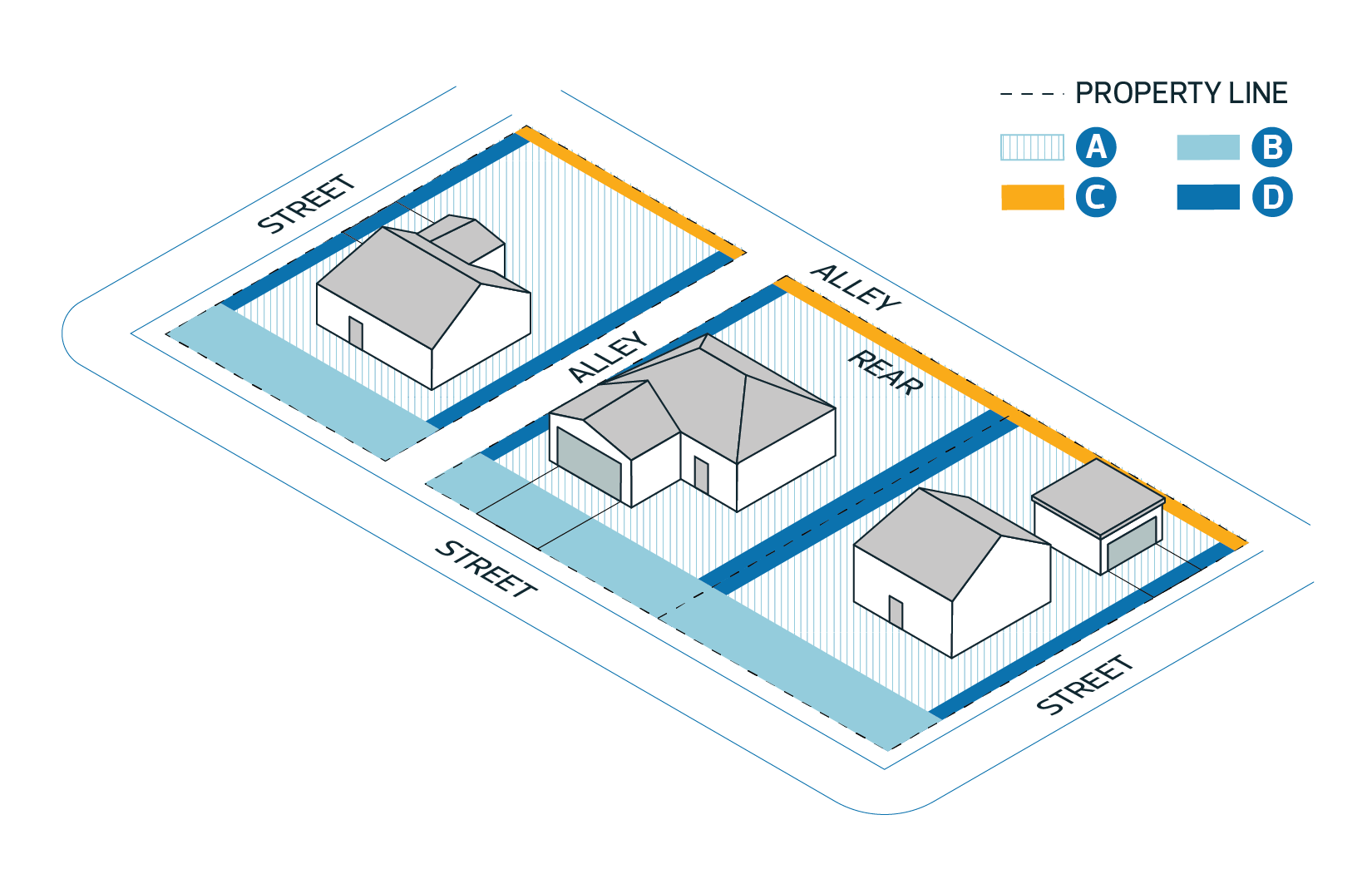
|
|||
| 3.3. | Despite Subsection 6.1.1 of Section 7.100, to prevent visual intrusion or provide additional screening from Abutting Sites or Streets, the Development Planner may vary the Height of a Privacy Screen, or a portion of a Privacy Screen, in compliance with the following: | ||||
|
5.110 Safe Urban Environments
| 1.1. | All developments must include the following design elements to promote a safe urban environment by providing natural surveillance, clear sightlines and wayfinding: | ||||||||||||
|
|||||||||||||
| 1.2. | Despite Subsection 1.1, this Section does not apply to: | ||||||||||||
|
|||||||||||||
| 2.1. | The Development Planner must require a Crime Prevention Through Environmental Design (CPTED) assessment as part of a Development Permit application where the proposed development includes: | ||||||||||||||||||||||||||||||||||||||
|
|||||||||||||||||||||||||||||||||||||||
| 2.2. | The Development Planner may require a CPTED assessment as part of a Development Permit application to determine if a development complies with Subsection 1.1. | ||||||||||||||||||||||||||||||||||||||
| 2.3. | A CPTED assessment must be prepared by a qualified security consultant, architect, or similar professional. | ||||||||||||||||||||||||||||||||||||||
| 2.4. | A CPTED assessment must include: | ||||||||||||||||||||||||||||||||||||||
|
|||||||||||||||||||||||||||||||||||||||
| 2.5. | The Development Planner may apply conditions to a Development Permit based on the recommendations of a CPTED assessment. |
5.120 Site Performance Standards
| 1.1. | Non-Industrial development must comply with the following: | ||||||||||
|
| 2.1. | Where a proposed non-Residential Use or Home Based Business may create a Nuisance, as determined at the time of the Development Permit application, mitigation measures to reduce any negative impacts must be provided to the satisfaction of the Development Planner, including: | ||||||||||
|
|||||||||||
| 2.2. | The Development Planner may impose conditions on a Development Permit to require the implementation of mitigation measures to ensure compliance with Subsection 2.1. |
| 3.1. | Outdoor lighting must: | |||||||||||
|


| 4.1. | Waste collection and disposal areas for Residential development must be designed to: | ||||||||||||||||||
|
|||||||||||||||||||
| 5.1. | The following vehicles are not permitted to be parked on any part of a Site in a residential Zone: | ||||||||||
|
|||||||||||
| 5.2. | A large Recreational Vehicle is not permitted in a Front Yard or in a Flanking Side Yard of a Residential Site for longer than reasonably necessary to load or unload the vehicle. | ||||||||||
| 5.3. | Despite Subsection 5.2, large Recreational Vehicles may park from April 1 to October 31 inclusive, on a Driveway leading to a Garage in a Front Yard or in a Flanking Side Yard of a Residential Site: | ||||||||||
|
|||||||||||
| 5.4. | For the purposes of Subsections 5.2 and 5.3, a large Recreational Vehicle does not include: | ||||||||||
|
| 6.1. | Where developments, such as Row Housing, require surface drainage to cross 1 or more Lots, all affected Lots must register a private drainage easement allowing the uninhibited flow of water across these Lots. |
5.130 Unique Lot Conditions
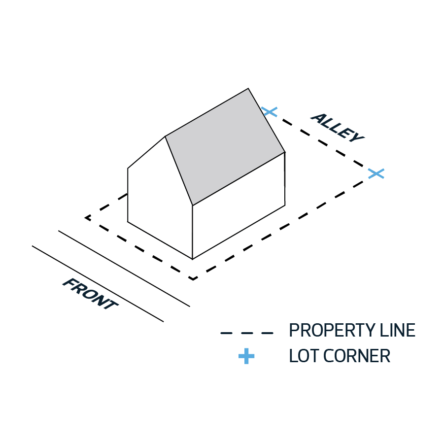
| 1. | On Corner Sites consisting of more than 1 Lot, the Front Lot Line of the Site is the same as the Front Lot Line of the Corner Lot. | |||
|
||||
| 2. | If the 2 Lot lines of a Corner Site Abutting a Street are equal in length, the location of the Front Lot Line of the Site must be determined by the Development Planner. The Development Planner must consider the orientation and access to the proposed development, and the Front Lot Lines of Abutting Lots when making this decision. | |||
| 3. | Despite Subsections 1 and 2 and the definition of Front Lot Line, the Development Planner may determine that a Corner Site has additional Front Lot Lines other than what is required. The Development Planner must consider the orientation and access to the proposed development, and the Front Lot Lines of Abutting Lots when making this decision. | |||
| 4. | Double Fronting Sites must have 2 Front Lot Lines. | |||
|
a | |||
| 5. | To determine if a Lot or Site along a curved Street is a Corner Lot or Corner Site, the Development Planner must take into account the angle where the lines tangent to each of the two endpoints of the curved Lot or Site intersect. | |||
| 6. | The corner of a Corner Lot or Corner Site is the point on the curved Lot line(s) that is closest to the two intersecting tangent lines described in Subsection 5. | a | ||
|

